![8.59 [3G Mechanical Tee Grooved Outlet] [FM, UL, VdS, CNBOP] Red.jpg](/media/4398/859-3g-mechanical-tee-grooved-outlet-fm-ul-vds-cnbop-red.jpg)
![8.59 [3G Mechanical Tee Grooved Outlet] [FM, UL, VdS, CNBOP] Galvanised.jpg](/media/4399/859-3g-mechanical-tee-grooved-outlet-fm-ul-vds-cnbop-galvanised.jpg)
3G Mechanical Tee Grooved Outlet
| Size range | DN50 x DN32 to DN100 x DN32 (2" x 1¼" to 4" x 3") |
|---|---|
| Maximum working pressure | Up to 20.7 bar (300 psi)* *depending on size and certification, please refer to Data Sheet 8.59 |
| Working temperature | -34°C to 110°C (-30°F to 230°F) |
| Gasket type | EPDM |
| Outlet connection | Grooved |
| Material | Ductile Iron |
| Finish | Red painted or Galvanised |
| Approvals | FM Approved, UL Listed, VdS, CNBOP |
Rapidrop Grooved couplings and fittings are used in the assembly of grooved piping systems. They are available in painted and galvanised finishes and are FM, UL Vds and CNBOP approved. The Rapidrop type 3G Mechanical tees are pressure rated to 300psi and are used to create a quick and easy pipe oulet. They can be used in standard and thin walled pipes.
Sizes & Dimensions
| Nominal Size mm/in |
Pipe O.D mm/in |
Working Pressure PSI/MPa |
Hole Dia mm/in +1.6,0/+0.063,0 |
Dimensions | Bolt Size | |||
| A mm/in |
B mm/in |
C mm/in |
D mm/in |
No.-Size mm |
||||
| 50 × 32 2 × 1¼ |
60.3 × 42.4 2.375 × 1.660 |
300 2.07 |
45 1.75 |
116 4.57 |
76 2.99 |
69.5 2.74 |
39 1.54 |
3/8 × 55 M10X57 |
| 50 × 40 2 × 1½ |
60.3 × 48.3 2.375 × 1.900 |
300 2.07 |
45 1.75 |
116 4.57 |
76 2.99 |
69.5 2.74 |
39 1.54 |
3/8 × 55 M10X57 |
| 65 x 32 2½ x 1¼ |
76.1 × 42.4 3.000 × 1.660 |
300 2.07 |
51 2.00 |
137 5.39 |
84.5 3.33 |
78 3.07 |
49.5 1.95 |
1/2 × 70 M12X70 |
| 65 x 40 2½ x 1½ |
76.1 × 48.3 3.000 × 1.900 |
300 2.07 |
51 2.00 |
137 5.39 |
84.5 3.33 |
78 3.07 |
49.5 1.95 |
1/2 × 70 M12X70 |
| 80 × 32 3 × 1¼ |
88.9 × 42.4 3.500 × 1.660 |
300 2.07 |
51 2.00 |
152 5.98 |
85.5 3.37 |
84.5 3.33 |
56.5 2.22 |
1/2 × 75 M12X76 |
| 80 × 40 3 × 1½ |
88.9 × 48.3 3.500 × 1.900 |
300 2.07 |
51 2.00 |
152 5.98 |
85.5 3.37 |
84.5 3.33 |
56.5 2.22 |
1/2 × 75 M12X76 |
| 80 × 50 3 × 2 |
88.9 × 60.3 3.500 × 2.375 |
300 2.07 |
64 2.50 |
152 5.98 |
98 3.86 |
84.5 3.33 |
56.5 2.22 |
1/2 × 75 M12X76 |
| 100 x 32 4 x 1¼ |
114.3 x 42.4 4.500 x 1.660 |
300 2.07 |
51 2.00 |
188 7.40 |
89 3.50 |
102 4.02 |
70 2.76 |
1/2 × 75 M12X76 |
| 100 × 40 4 × 1½ |
114.3 × 48.3 4.500 × 1.900 |
300 2.07 |
51 2.00 |
188 7.40 |
89 3.50 |
102 4.02 |
70 2.76 |
1/2 × 75 M12X76 |
| 100 × 50 4 × 2 |
114.3 × 60.3 4.500 × 2.375 |
300 2.07 |
64 2.50 |
188 7.40 |
104.5 4.11 | 102 4.02 |
70 2.76 |
1/2 × 75 M12X76 |
| 100 × 65 4 × 2½ |
114.3 × 76.1 4.500 × 3.000 |
300 2.07 |
70 2.75 |
188 7.40 |
104.5 4.11 |
102 4.02 |
70 2.76 |
1/2 × 75 M12X76 |
| 100 × 80 4 × 3 |
114.3 × 88.9 4.500 × 3.500 |
300 2.07 |
89 3.5 |
188 7.40 |
125 5.03 |
102 4.02 |
70 2.76 |
1/2 × 75 M12X76 |
| 125 × 50 5 × 2 |
139.7 × 60.3 5.500 × 2.375 |
300 2.07 |
64 2.5 |
221.5 8.72 |
112.5 4.43 |
118 4.65 |
84 3.31 |
5/8 × 85 M16X85 |
| 125 × 65 5 x 2½ |
139.7 × 76.1 5.500 × 3.000 |
300 2.07 |
70 2.75 |
221.5 8.72 |
112.5 4.43 |
118 4.65 |
84 3.3 |
5/8 × 85 M16X85 |
| 125 × 80 5 x 3 |
139.7 × 88.9 5.500 × 3.500 |
300 2.07 |
89 3.5 |
221.5 8.72 |
132 5.20 |
118 4.65 |
84 3.3 |
5/8 × 85 M16X85 |
| 150 x 32 6 x 1¼ |
168.3 × 42.4 6.500 × 1.660 |
300 2.07 |
51 2.00 |
240 9.45 |
92.5 3.64 |
126 4.96 |
96.5 3.80 |
5/8 × 105 M16X108 |
| 150 × 40 6 × 1½ |
168.3 × 48.3 6.500 × 1.900 |
300 2.07 |
51 2.00 |
247 9.72 |
95 3.74 |
128 5.04 |
98.5 3.88 |
5/8 × 105 M16X108 |
| 150 × 50 6 × 2 |
168.3 × 60.3 6.625 × 2.375 |
300 2.07 |
64 2.5 |
247 9.72 |
114 4.49 |
134 5.28 |
98.5 3.88 |
5/8 × 105 M16X108 |
| 150 × 65 6× 2½ |
168.3 × 76.1 6.625 × 3.000 |
300 2.07 |
70 2.75 |
247 9.72 |
112.5 4.43 |
135 5.32 |
98.5 3.88 |
5/8 × 105 M16X108 |
| 150 × 80 6 × 3 |
168.3 × 88.9 6.625 × 3.500 |
300 2.07 |
89 3.50 |
247 9.72 |
160 6.30 |
141 5.55 |
98.5 3.88 |
5/8 × 105 M16X108 |
| 150 × 100 6 × 4 |
168.3 × 114.3 6.625 × 4.500 |
300 2.07 |
114 4.50 |
247 9.72 |
156.5 6.16 |
138 5.43 |
98.5 3.88 |
5/8 × 105 M16X108 |
| 200 x 65 8 × 2½ |
219.1 × 76.1 8.625 × 3.000 |
300 2.07 |
70 2.75 |
320 12.60 |
118 4.65 |
158 6.22 |
125 4.92 |
3/4 × 115 M20X115 |
| 200 × 80 8 × 3 |
219.1 × 88.9 8.625 × 3.500 |
300 2.07 |
89 3.50 |
320 12.60 |
136.5 5.37 |
161 6.34 |
125 4.92 |
3/4 × 115 M20X115 |
| 200 × 100 8 × 4 |
219.1 × 114.3 8.625 × 4.500 |
300 2.07 |
114 4.50 |
320 12.60 |
162 6.38 |
161 6.34 |
125 4.92 |
3/4 × 115 M20X115 |
Specified Bolt Torque ANSI BOLTS
| Bolt Size inch |
Specified Bolt Torque | |
| Lbs-Ft. | N.m | |
| 3/8 | 30-45 | 40-60 |
| 1/2 | 80-100 | 110-135 |
| 5/8 | 100-130 | 135-175 |
| 3/4 | - | - |
| 7/8 | - | - |
Related Products
3G Mechanical Tee Grooved Outlet
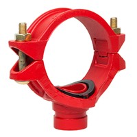
Mechanical tee grooved outlet in sizes from 50mm x 32mm (2" x 1¼") to 100mm x 80mm (4" x 3")
View Full DetailsModel E Wet Alarm Valve (Grooved / Grooved)
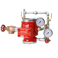
Sizes 100mm to 150mm (4" to 6"), FM Approved, UL Listed, LPCB, CE, Gost
View Full Details701 Y-Type Strainer (Grooved)
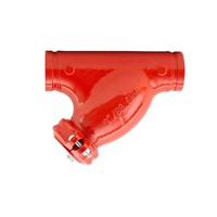
Grooved Y-Type Strainer with connection sizes 50mm - 300mm (2" - 12") UL Listed
View Full Details216 Butterfly Valve (Grooved)
50mm - 300mm (2" - 12"), FM Approved, UL listed, VdS, Gost
View Full Details103GG OS&Y Resilient Wedge Gate Valve
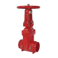
65mm - 400mm (2½" - 16"), UL Listed, FM approved, Gost
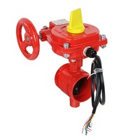
View Full Details114GG NRS PIV Gate Valve (Grooved)
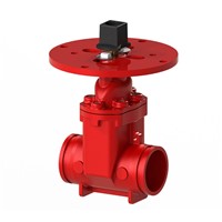
100mm - 300mm (4" - 12"), FM Approved, UL Listed
View Full Details