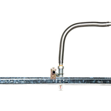
SMB Flexible Sprinkler Connection
| Hose Type | Braided Stainless Steel Flexible |
|---|---|
| Lengths | 780mm, 1000mm, 1220mm, 1540mm, 1830mm |
| Hose Size | 1" (DN25) |
| Maximum Working Pressure | 12 bar / 175 PSI |
| Minimum Bend Radius | 165mm / 6½” |
| Inlet connection | 1” NPT/ 1” BSPT |
| Straight outlet | ½" NPT or ¾" NPT internal thread (optional BSPT)½” NPT / ½” BSPT or ¾” NPT / ¾” BSPT |
| 90° outlet elbow | ½" NPT or ¾" NPT standard or long radius |
| Minimuim K-Factor | K5.6 (K80) with ½” outlet |
| Maximum K-Factor | K14 (K200) with ¾” outlet |
| Approvals | FM Approved |
Rapidrop Flexible Sprinkler Hose connects the sprinkler to the branch line. The flexible stainless steel hose and fittings are particularly suited for use in suspended ceiling applications. The Rapidrop assembly comes with one stainless steel flexible hose, one branch line connection nipple, one sprinkler reducer and a set of fixing brackets. Flexible stainless steel hoses are available in lengths 780 - 1830mm (31” – 72”) with either ½” or ¾” NPT / BSPT threaded outlets. Rapidrop Flexible Sprinkler Hoses are approved by FM and were tested in accordance with FM1637.
The Original and first European Flexible Sprinkler Connection
Traditionally, sprinklers installed in suspended ceilings required an arm over using rigid pipe connections which have to be measured, cut and threaded on site using trial and error techniques. This process is time consuming and expensive and can take more than 1 hour to install each sprinkler.
Rapidrop, the original and first European approved alternative solution to traditional pipe work reduces installation time and costs. Rapidrop is an adjustable corrugated stainless steel connection that removes the need for cutting, threading and precise measurements. Rapidrop Flexible Sprinkler Connections can easily be formed by hand connecting the sprinkler to the pipework quickly even in the most restricted spaces, voids as small as 100mm.
Millions of Rapidrops have now been installed worldwide. The result is a proven and reliable connection for sprinklers in suspended ceilings, even when the sprinklers are operating at maximum pressure there are no adverse effects upon the ceiling suspension system.
The benefits of using Rapidrops are considerable for the installer and the building owner, no measuring, cutting, threading or welding, no oils, grease or mess and the Rapidrop is self-supporting so no intermediate supports are required on lengths below 1.6 metres. No special equipment is required, using only normal hand tools installers can achieve centre of tile and correct vertical position first time every time. Full system pressure test can be achieved at first fix stage, no need to drain down for second fix, just depressurise, therefore no system refill or second pressure test is required.
A large range of ceiling support brackets are available to suit different ceiling systems including lift out tile, fixed board for example Gypsum and many other types. The range of brackets are suitable for use with all sprinklers such as concealed, flush pendent and pendent heads. All Rapidrop connection nipples incorporate a unique tapered seal profile giving enhanced sealing reliability plus a fine metric thread that connects directly to the tube nut and avoids confusion with mating pipe threads. With numerous inlet, outlet and bracket options, Rapidrop are supplied in kit form from the factory containing only the specific components as per your order.
Following extensive testing, Rapidrop SMB Flexible Sprinkler Connection is approved and listed by Factory Mutual (FM)
Rapidrop has become the industry standard method for connection to sprinklers in suspended ceilings and has been installed on many large building projects including Canary Wharf Development London.
Technical Details
| Max. Working Pressure | 12 bar / 175 PSI |
| Max. Ambient Temperature | 107°C / 225°F |
| Min. Bend Radius of Flexible Hose | 165mm / 6½” |
| Connection to Branch Line (Inlet) | 1” NPT/ 1” BSPT |
| Connection to the Sprinkler (Outlet) | ½” NPT / ½” BSPT or ¾” NPT / ¾” BSPT |
| Min K-Factor | K5.6 (K80) with ½” outlet |
| Max K-Factor | K14 (K200) with ¾” outlet |
Pressure Loss Data
Models with Straight Outlet
| Model |
Minimum Bend Radius |
Number of Bends | Rated Working Pressure |
Hose Assembly length |
Equivalent Length of 1 in. Schedule 40 Pipe | |||
| 1/2” outlet K5.6 (K80) |
3/4” outlet K8.0 (K115) |
3/4” outlet K11.2 (K160) |
3/4” outlet K14 (K200) |
|||||
| in. mm | psi kPa | in. mm | ft. m | ft. m | ft. m | ft. m | ||
| SMB01 | 6 ½ 165 |
1 | 175 1205 |
31 780 |
23 7 |
16.8 5.1 |
17.7 5.4 |
18.4 5.6 |
| SMB02 | 3 | 39 1000 |
31.4 9.6 |
25.8 7.9 |
25.8 7.9 |
25.9 7.9 |
||
| SMB03 | 3 | 48 1220 |
39.8 12.1 |
33.5 10.2 |
33.5 10.2 |
33.4 10.2 |
||
| SMB04 | 4 | 60 1540 |
45.6 13.9 |
40.7 12.4 |
40.7 12.4 |
40.8 12.4 |
||
| SMB05 | 4 | 72 1830 |
50.9 10.5 |
47.2 14.4 |
47.6 14.5 |
47.6 14.5 |
||
Pressure Loss Data
Models with 90° Elbow Outlet
| Model |
Minimum Bend Radius |
Number of Bends | Rated Working Pressure |
Hose Assembly length |
Equivalent Length of 1 in. Schedule 40 Pipe | |||
| 1/2” outlet K5.6 (K80) |
3/4” outlet K8.0 (K115) |
3/4” outlet K11.2 (K160) |
3/4” outlet K14 (K200) |
|||||
| in. mm | psi kPa | in. mm | ft. m | ft. m | ft. m | ft. m | ||
| SMB01 | 6 ½ 165 |
1 | 175 1205 |
31 780 |
27.2 8.3 |
22.8 6.9 |
22.6 6.9 |
21.9 6.7 |
| SMB02 | 3 | 39 1000 |
33.7 10.2 |
26.8 8.1 |
26.2 7.9 |
25.9 7.9 |
||
| SMB03 | 3 | 48 1220 |
40 12.2 |
30.9 9.4 |
29.9 9.1 |
30 9.1 |
||
| SMB04 | 4 | 60 1540 |
49.6 15.1 |
40.9 12.5 |
40.1 12.2 |
41.1 12.5 |
||
| SMB05 | 4 | 72 1830 |
58.4 17.8 |
49.9 15.2 |
49.4 15 |
51.2 15.6 |
||
Note: Table above shows pressure loss figures for the flexible hose with maximum number of bends. Pressure loss of the hose with fewer bends than shown in the table will be lower.
Related Products
RD105 Commercial Flat Concealed Pendent Sprinkler
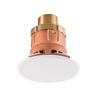
K5.6 Commercial Flat Concealed Sprinkler Pendent, cULus Listed, FM Approved
View Full DetailsRD023 SSP Pendent Quick Response Sprinkler
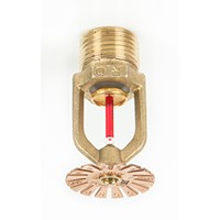
K80 (K5.6) SSP Pendent Quick Response Fire Sprinkler, 15mm (½”), FM approved, cULus Listed, LPCB, VdS, CE
View Full DetailsTwo Piece Escutcheon
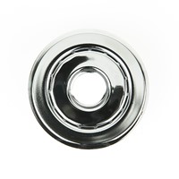
Recessed two piece push fit rosette suitable for most 15mm (½”) pendent sprinkler heads
View Full Details