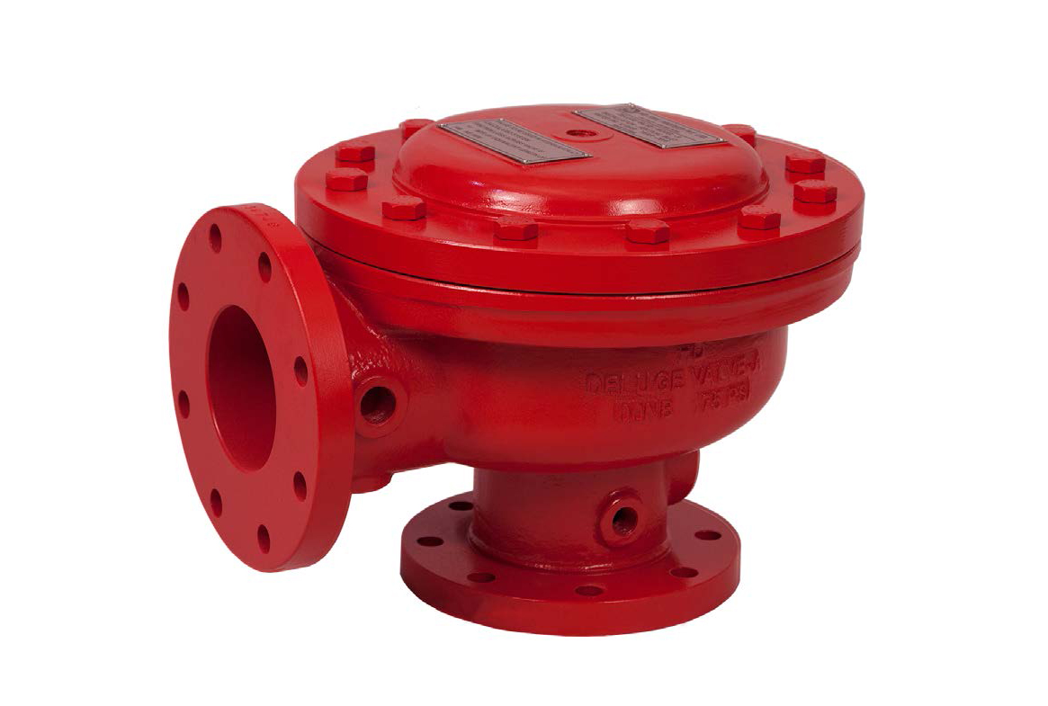
Model A Deluge Valve
| Size range | 2” (50 mm) - 8” (200 mm) |
|---|---|
| Working pressure | 12 Bar (175 psi) |
| Threaded Opening | BSPT |
| Mounting | 90° pattern inlet to outlet vertical mounting. |
| Factory Hydrostatic Test Pressure | 25 Kg./sq.cm. ( 350 psi ) |
| Flange Connection | ANSI B 16.1 FF #125 |
| Trim | Galvanized steel with brass valves |
| Finish | Fire red PU painted |
| Approvals | UL Listed |
Deluge Valve is known as a system control valve in a deluge system, used for fast application of water in a spray system. Deluge valve protects areas such as power transformer installation, storage tank, conveyor protection and other industrial application etc. With the addition of a foaming agent they protect aircraft hangers and inflammable liquid fire.
Valve Operation
Deluge valve is a quick release, hydraulically operated diaphragm valve. It has three chambers, isolated from each other by the diaphragm operated clapper and seat seal. While in ‘SET’ position, water pressure is transmitted through an external bypass check valve and restriction orifice from the system supply side to the top chamber, so that supply pressure in the top chamber acts across the diaphragm operated clapper which holds the seat against the inlet supply pressure because of differential pressure design. On detection of fire, the top chamber is vented to atmosphere through the outlet port via opened actuation device(s). The top chamber pressure cannot be replenished through the restricted inlet port, thus it reaches less than half the supply pressure instantaneously and the upward force of the supply pressure lifts the clapper allowing water to enter the system piping network and alarm devices.
Trim Description
a) Basic Trim
The basic trim is required on deluge valve regardless of the release system. It contains those components which are required for all types of installation, such as the main drain valve, priming connection, drip check valve, emergency release valve and pressure gauges.
b) Dry Pilot Trim (Pneumatic Release)
The dry pilot operation uses a pilot line of closed Sprinklers/ QB detectors containing air under pressure, located in the area to be protected. It requires regulated dry air supply with main supply point through a restricted orifice. The pilot line is connected directly to the top of POSITIVE DRAIN ACTUATOR (PDA). The bottom of PDA is connected to the top chamber of the deluge valve. When the air pressure drops, due to a release of any of the release devices on detection of fire, the diaphragm of PDA is lifted and allows the water to drain. This reduces the water pressure in the top chamber of the deluge valve and when the pressure in the top chamber reaches 50% of the supply pressure, the deluge valve opens. The direct drain of PDA starts when the top chamber pressure of deluge valve reaches approximately 0.5 Kg/sq.cm. This positive drain will not permit the deluge valve to close unless the PDA is set manually. The recommended air supply pressure is as per TABLE-1.
c) Wet Pilot Trim ( Hydraulic Release )
The wet pilot operation uses a pilot line of closed sprinklers containing pressurised water, supplied through the upstream side of the deluge valve, through a restricted orifice. All the release lines are connected to a common release line. Due to the release of any one of the release devices, the water pressure in the top chamber of the deluge valve reaches 50% of the supply pressure, the deluge valve opens.